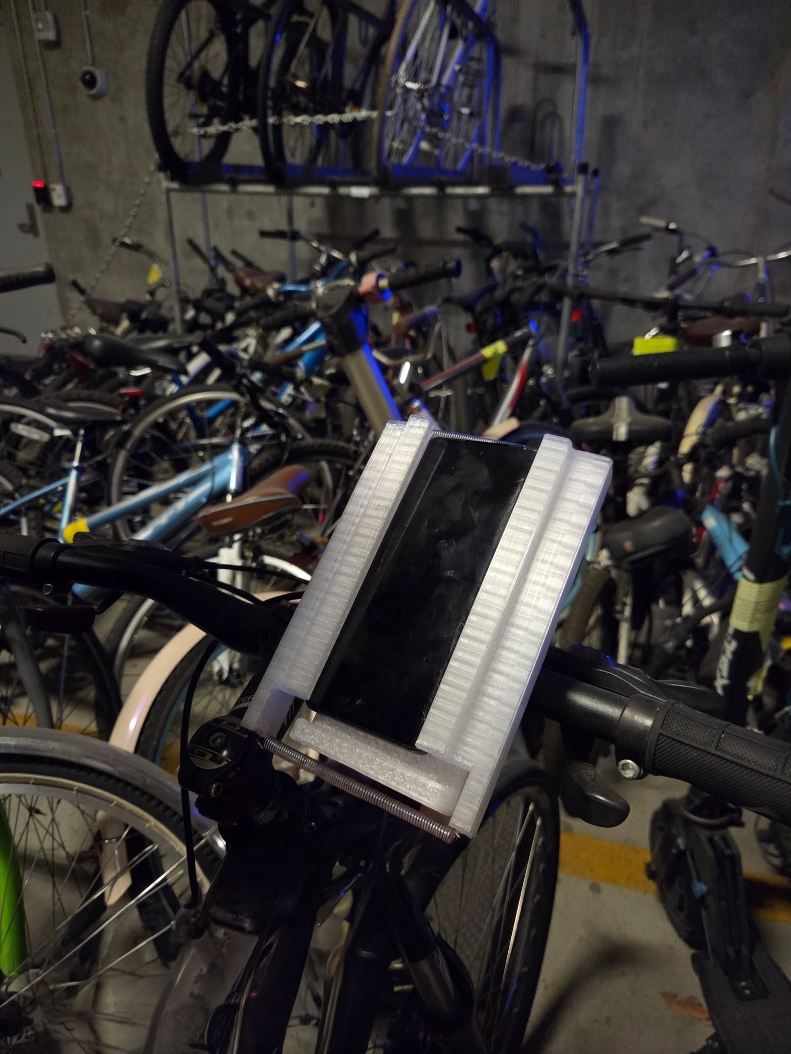
Bike Phone Holder
About Top-Down Modeling
Top-down modeling is a CAD workflow in which a design is developed by referencing shared geometry from a higher-level assembly or master layout. Rather than designing each component in isolation, the major interfaces are established first and then used to drive the dimensions and relationships of the individual parts. This approach is especially useful when several components must fit together precisely while remaining parametric.
For this project, a top-down workflow was used to develop a phone holder that mounts to bicycle handlebars and supports quick orientation changes between portrait and landscape modes.
Project Overview
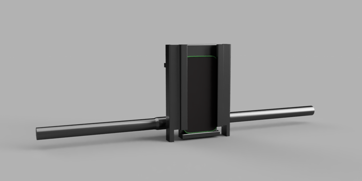
The goal of this project was to design a phone holder that could be attached to a bike without requiring tools for routine use. Once mounted, the holder needed to grip the phone securely, resist vibration, and allow rotation between portrait and landscape orientations. Because the phone and handlebar interfaces were the most important design constraints, the holder was modeled around those fixed reference points from the start. A top-down modeling workflow made it possible to maintain alignment between the bike mount and the rotating phone cradle. It also made later adjustments easier, since changes to one interface could propagate through the rest of the model.
Design Requirements
The test handlebars had a 25.4 mm clamp diameter and a 22.2 mm grip diameter; the phone holder needed to be able to mount on either width. The design had to be compatible with a range of phone sizes and attach quickly without separate tools. It also needed to use a detent mechanism with enough holding force to permit deliberate rotation while preventing accidental rotation.
Design Approach
The handlebar component was created and anchored as the initial fixed reference. From there, the mount, rotating cradle, and phone-retaining features were modeled as separate components.
Projected geometry was used selectively to maintain alignment between the phone, the mount, and the rotation mechanism. Because projected references can break when upstream geometry changes, the final model was cleaned up to preserve a stable parametric structure. This kept the CAD tree organized and reduced the risk of broken dependencies during later revisions.
Iteration 1
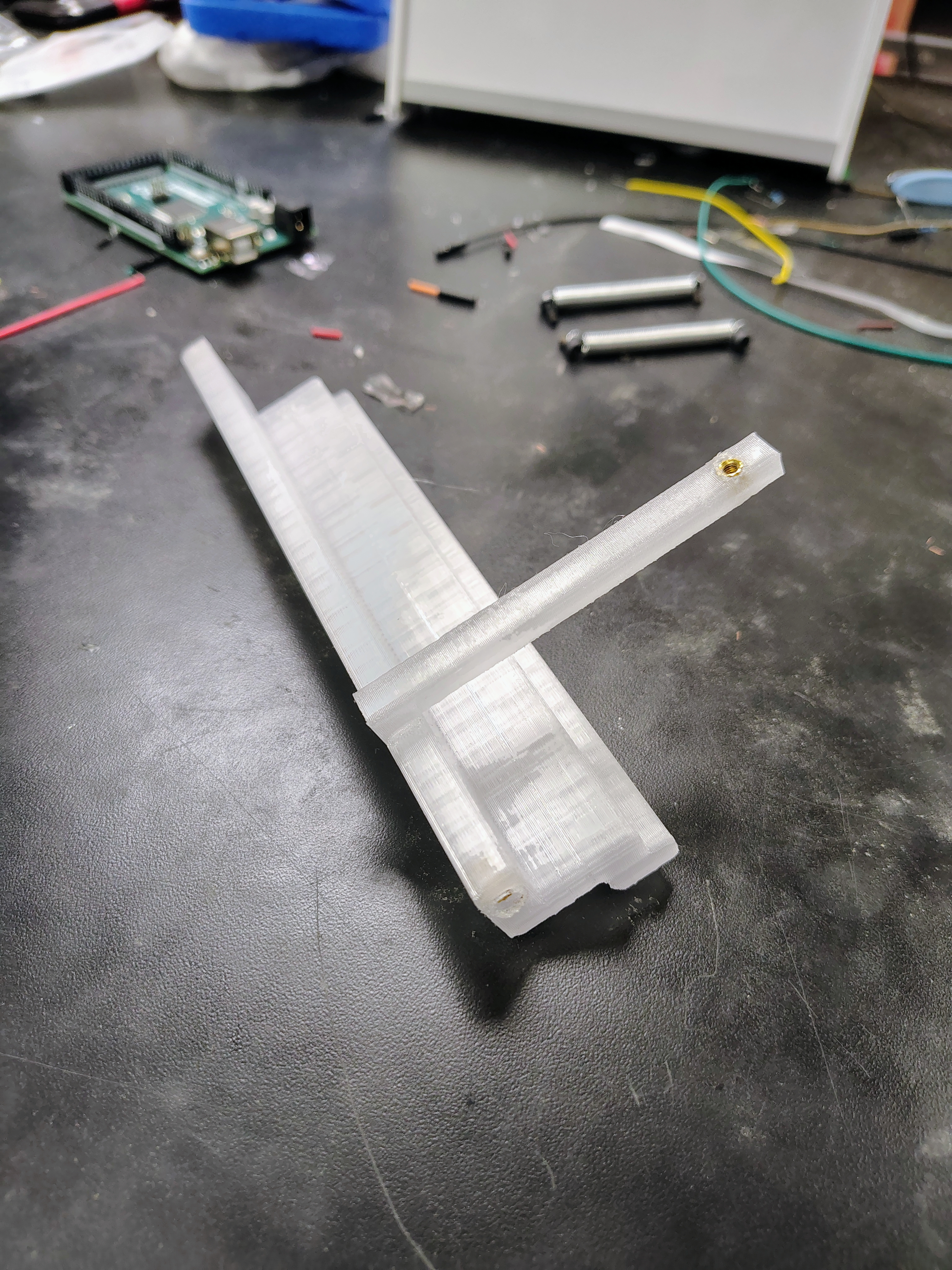
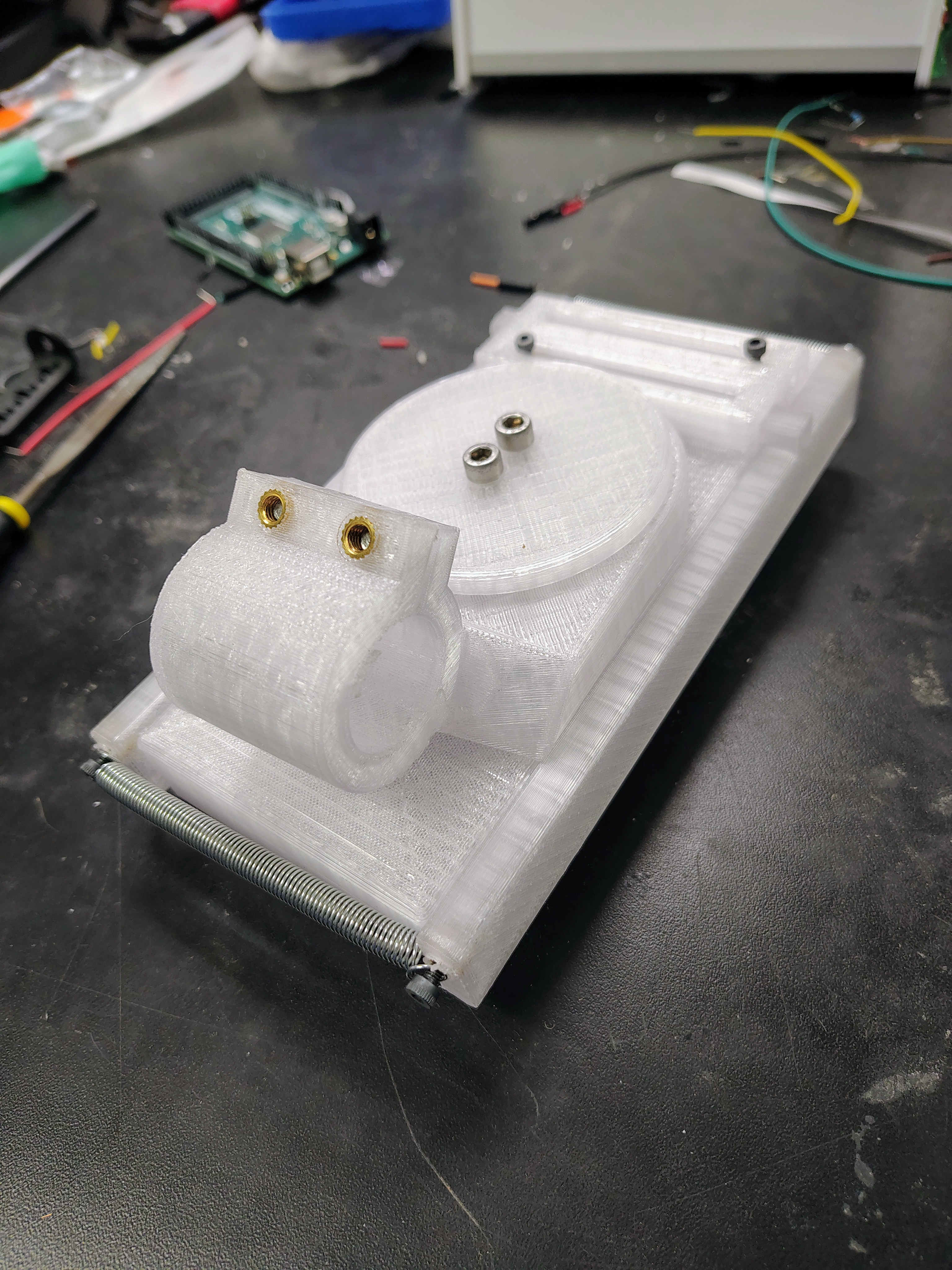
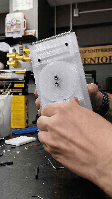
The first prototype was printed in PLA and consisted of six components, organized into three functional groups: the handlebar clamp, the phone cradle and rotation interface, and the phone retention system.
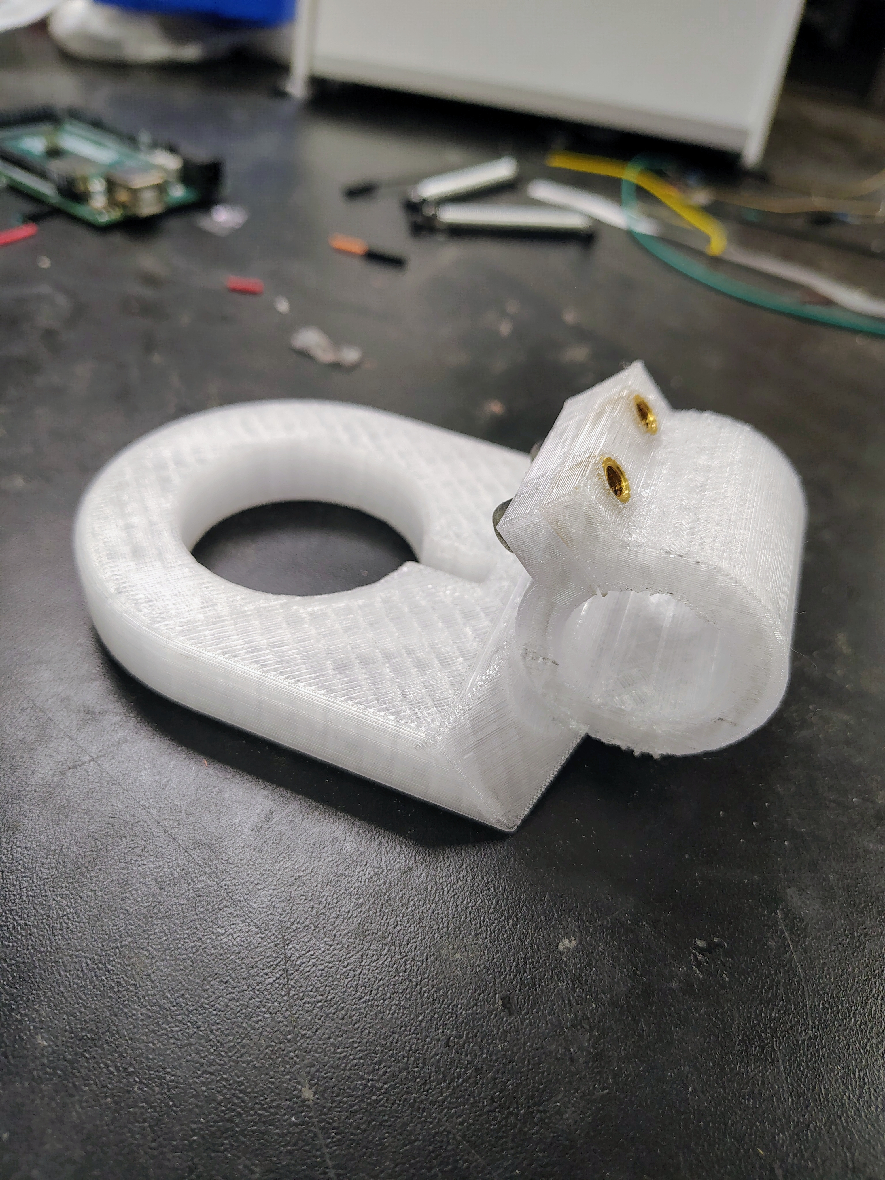
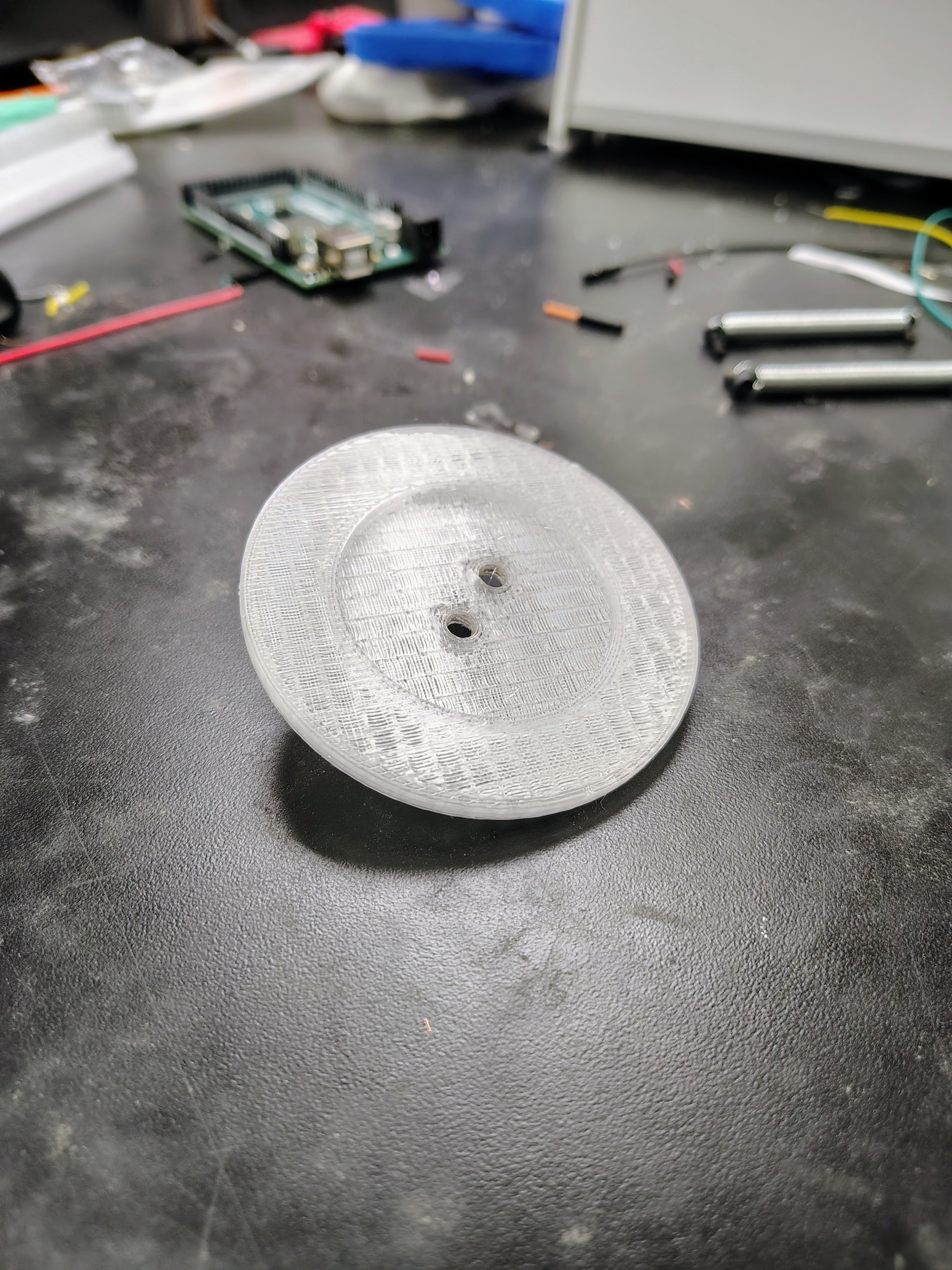
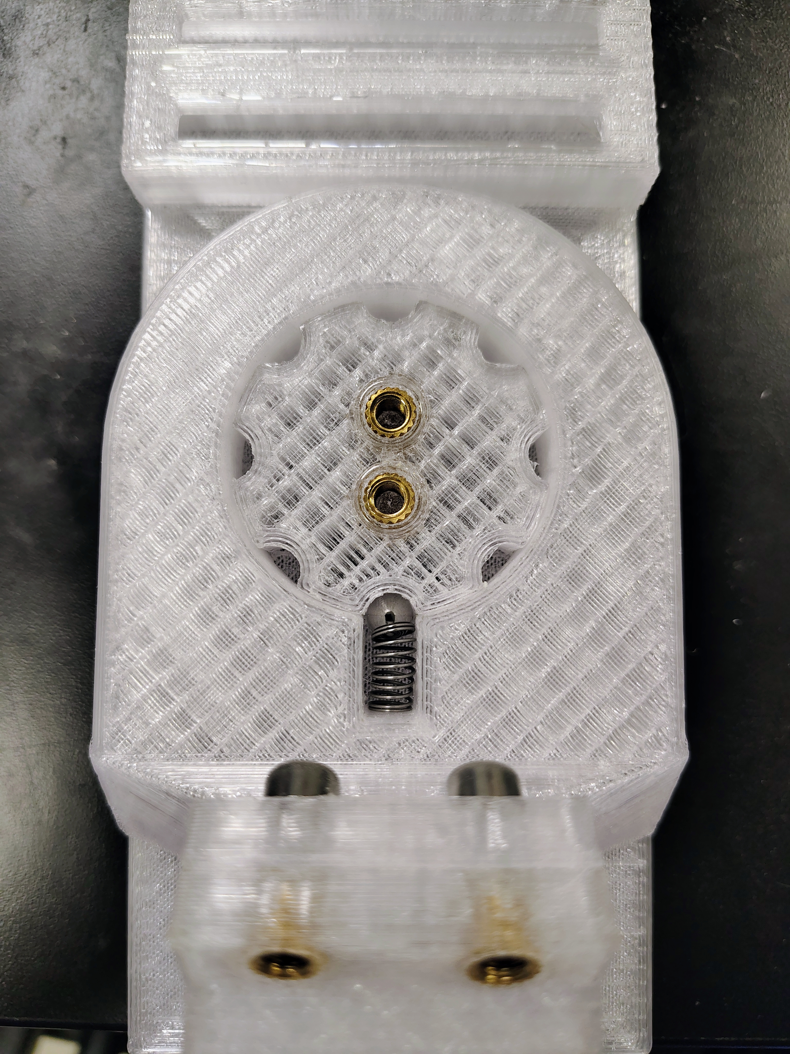
The handlebar clamp was composed of two mating halves that wrapped around the handlebar. One half was integrated with a base plate that included a circular recess used for the rotation interface, while the opposing half acted as a cap. These two components were fastened together using M5 bolts and heat-set inserts, allowing the device to clamp securely onto the handlebar.
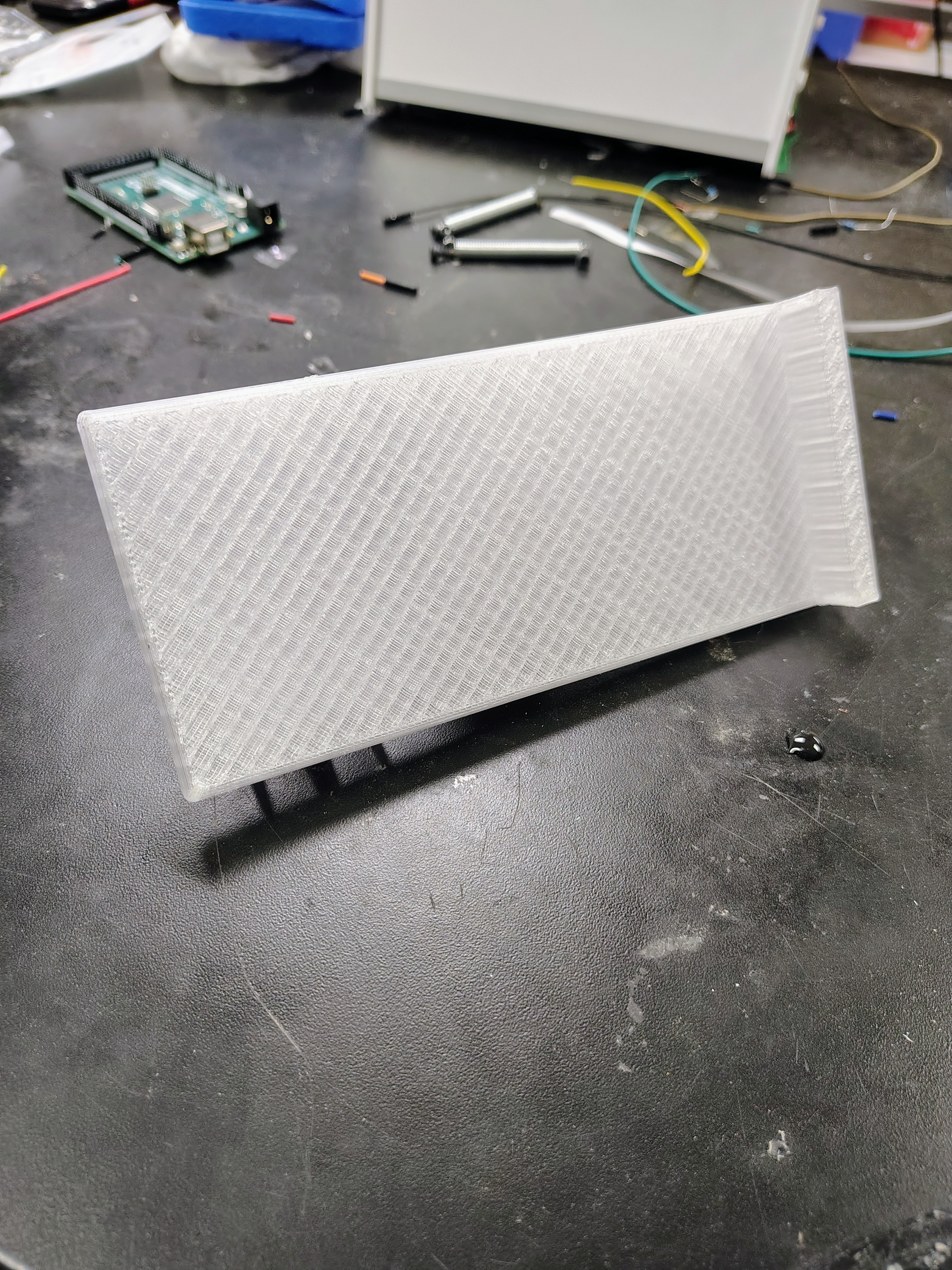
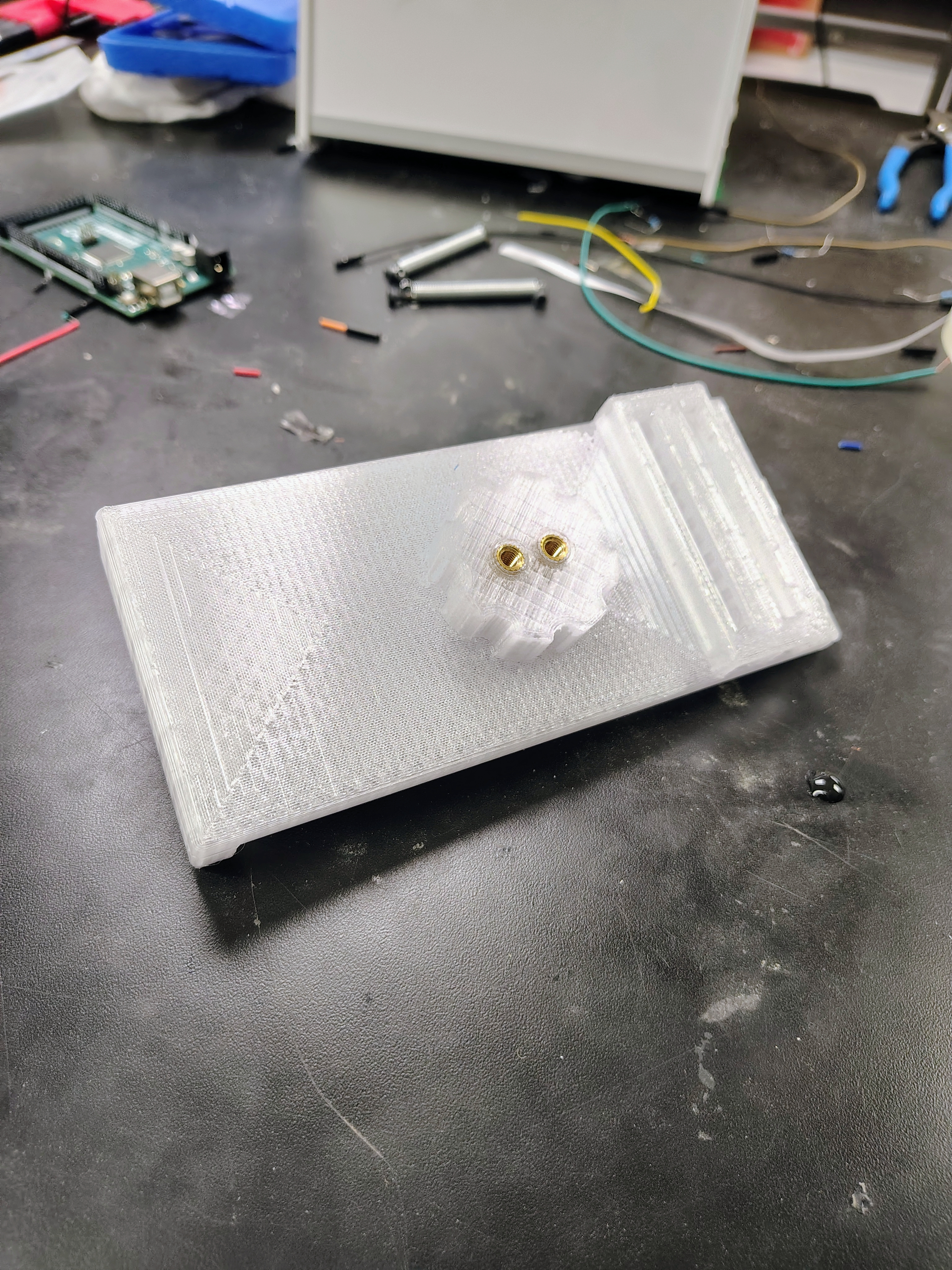
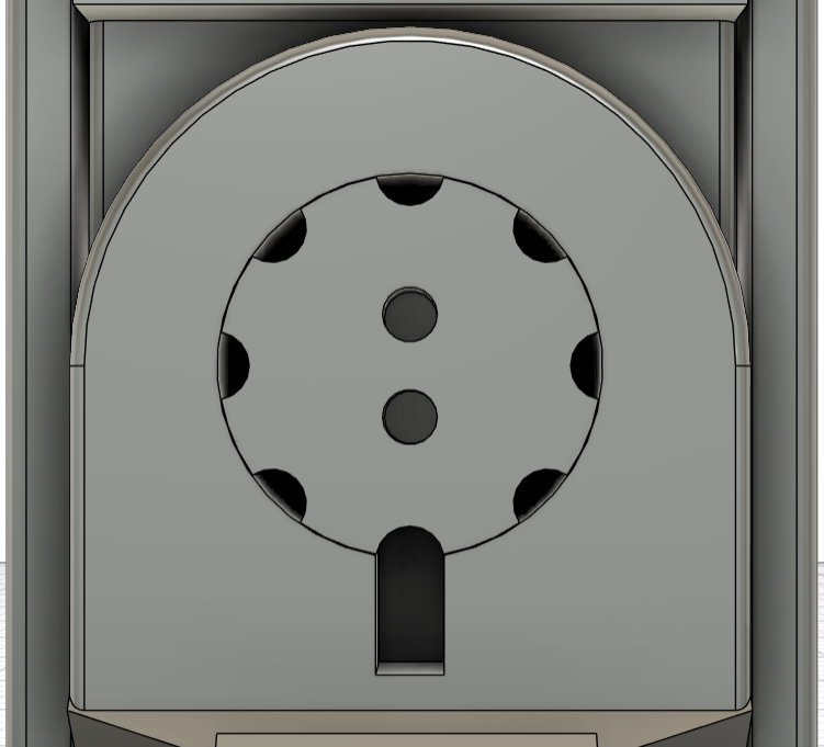
The phone cradle was designed as a flat platform with a bottom lip to support the phone. On the back side of this cradle, two key features were incorporated:
- Guide channels (rail passages) for the side retention components
- A rotational interface boss with eight evenly spaced detent notches
This boss interfaced with the circular recess on the clamp base to form the detent mechanism. A spring and ball bearing were inserted between these components so that the ball seated into the notches, producing discrete rotational positions and a tactile click between orientations.
A retaining cap (back cover) was added over this interface and fastened using M5 inserts and bolts to prevent the spring and ball from escaping during use.
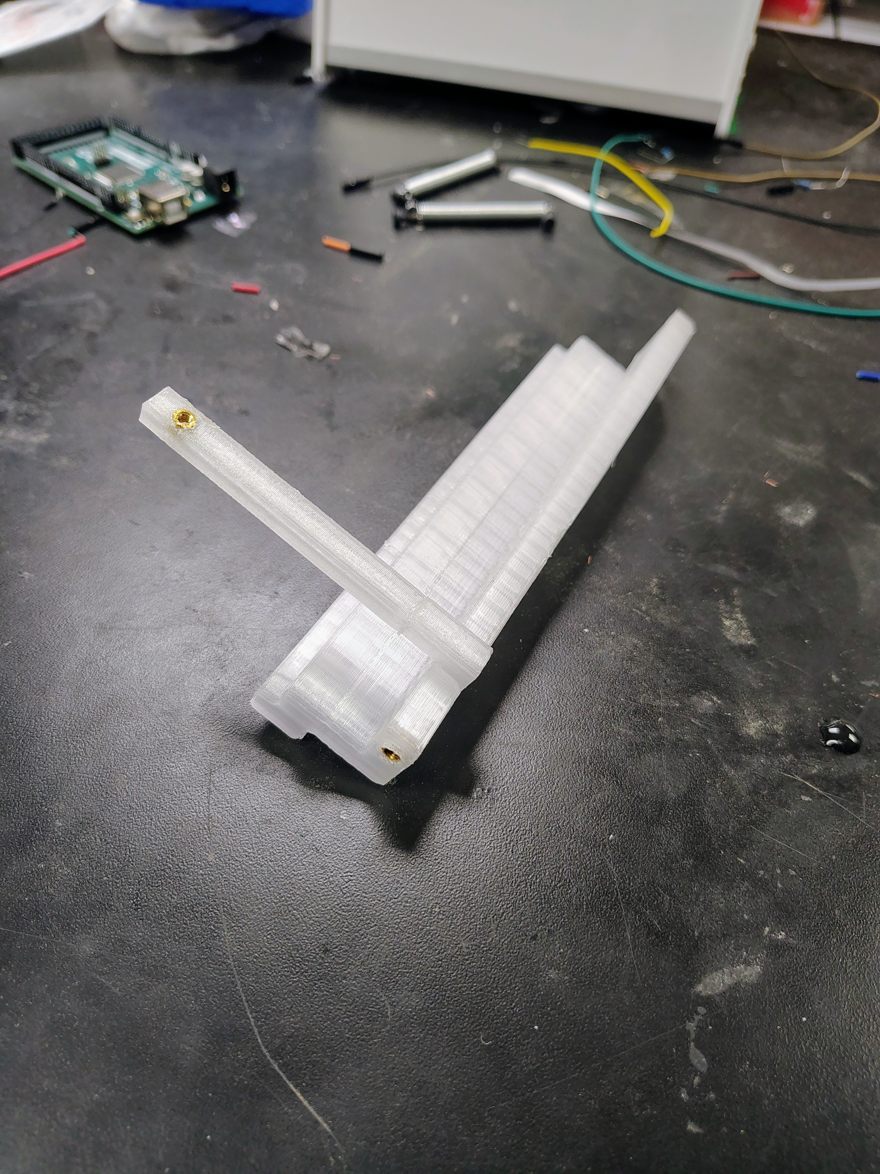
The phone retention system consisted of two sliding side clamps, each designed to move along the guide channels on the back of the cradle. These clamps were intended to hold the phone laterally. Each clamp included mounting points for M3 heat-set inserts, which were used to anchor springs between the upper and lower fasteners. This created a spring-loaded clamping force to secure the phone.
This iteration demonstrated that the detent mechanism functioned effectively, producing a clear and audible click at each rotational step. However, the design had two major issues:
- The side clamps did not fit into the guide channels due to oversized rail geometry
- The overall assembly was too bulky, making it impractical for real-world use
Iteration 2
The second prototype was printed in PETG and focused on simplifying the design while resolving the key issues identified in Iteration 1. PETG was used due to material constraints; under normal circumstances, PLA would have been used again due to its lower weight and more predictable dimensional accuracy.
The most significant change in this iteration was the redesign of the handlebar clamp as a single-piece split clamp. Instead of two separate halves, the clamp featured a continuous body with a 2 mm gap, allowing it to flex open slightly. M5 heat-set inserts were placed on one side of the gap, and bolts were driven through the opposite side to create a clamping mechanism. This reduced part count and improved ease of assembly.
The phone cradle and detent interface remained largely the same in concept, but the tolerances were adjusted to improve fit. The side clamps were also fixed so that their rails successfully fed through the guide channels on the back of the cradle. This allowed the spring-loaded retention system to function as originally intended.
However, the change in material introduced new challenges. Printing in PETG caused dimensional expansion and reduced tolerance accuracy, particularly in the detent interface. While the components assembled correctly, the rotation between positions became noticeably stiffer and less smooth. The detent still functioned, but the increased friction reduced the quality of the tactile feedback.
Despite this, Iteration 2 represented a meaningful improvement:
- Reduced part count and simplified assembly
- Functional phone retention system
- More compact geometry
The primary takeaway from this iteration was the strong influence of material choice on tolerances and mechanism performance, especially for precise features like rotating interfaces.
Detent Mechanism
The detent mechanism was incorporated to lock the phone into defined orientations. Its dimensions were parameterized so that the engagement force could be adjusted if the printed parts were too loose or too stiff. That flexibility is important in filament printing because clearance, surface finish, and layer adhesion can all affect how smoothly a rotating mechanism behaves. In practice, this made the detent one of the most important features to prototype early and refine through iteration.
Fabrication Process
The holder was fabricated using filament 3D printing. This choice was appropriate because the device needed to be structurally robust, relatively quick to iterate, and suitable for repeated assembly and disassembly. FFF printing in particular allowed for rapid prototyping and testing of small mechanical features, such as the detent mechanism, before committing to a full-scale design. It also provided a more cost-effective approach compared to resin printing, especially when multiple iterations were required. All printing was done on Voron printers.
Assembly and Use
The holder was assembled around the handlebar with M5 bolts and secured using the designed clamp interface. Once mounted, the phone could be inserted into the cradle and rotated between orientations until the detent engaged. The mechanisms in the final assembly effectively allowed for a stable, repeatable motion with enough holding force to resist vibration during riding.
Testing and Iteration
Testing focused on three main topics: whether the mount fit the handlebar correctly, whether the phone remained secure during vibration, and whether the detent produced a clear and reliable click between positions. Because printing tolerances can affect both grip and rotation, the mechanism was designed to be adjustable through parameter changes rather than rebuilt from scratch each time. If the fit was too tight, the clearances around the rotation joint could be increased. If the detent was too weak, spring preload or notch depth could be adjusted. If the parts flexed too much, the wall thickness or material choice could be revised in a later print.
Multimedia
Individual Components