Multi-Material Pliers
About Print-in-Place Parts
Print-in-place (PIP) parts are additively manufactured assemblies that emerge from the printer fully functional, requiring no post-print assembly. By strategically designing clearances, joints, and interfaces, multiple moving components can be implemented together in a single print. This approach reduces assembly time and part count, and enables mechanisms that would be difficult to produce using traditional manufacturing methods.
Print-in-place techniques have been used in many applications, including hinges, articulated toys, gears, and tools such as clamps. In engineering and prototyping contexts, PIP designs are especially valuable for rapid iteration, allowing designers to test mechanical concepts directly off the print bed.
Material selection plays an important role in print-in-place designs, especially when motion or load transfer is involved. Common single-material solutions include PLA and PETG due to their dimensional stability and ease of printing, while nylon offers improved toughness and wear resistance for moving components. In multi-material print-in-place applications, combining rigid materials with flexible elastomers (such as TPU) enables integrated compliance, grip surfaces, and spring mechanisms.
This project explores the design and fabrication of multi-material pliers that can be printed in-place (if using a multi-material FFF printer).
Iterative Process
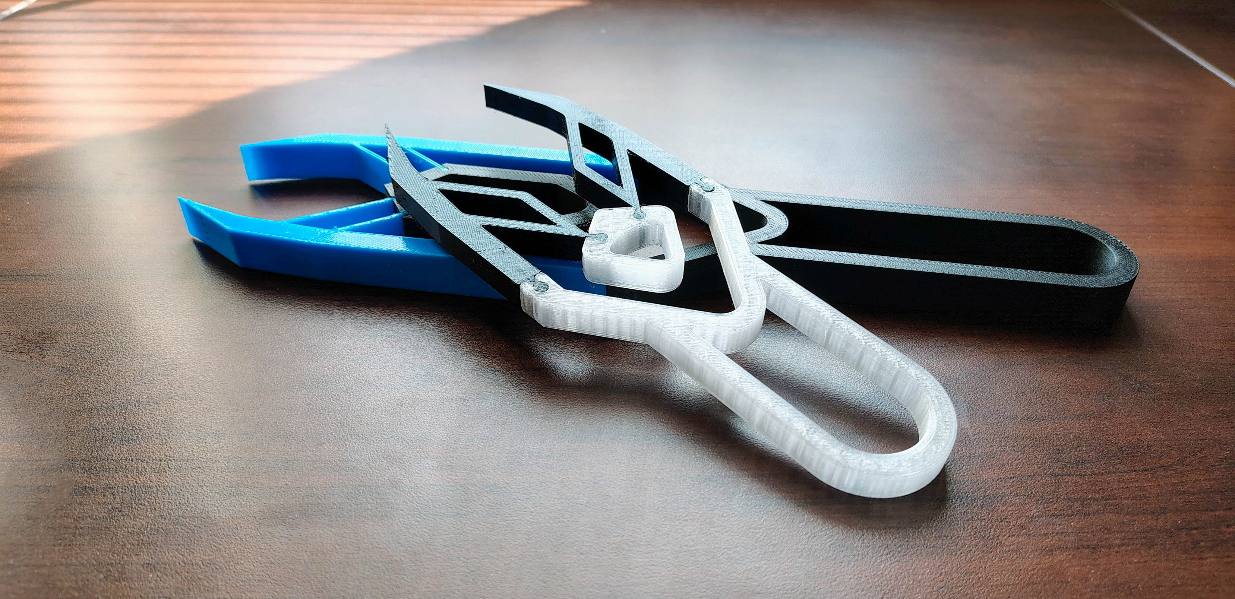
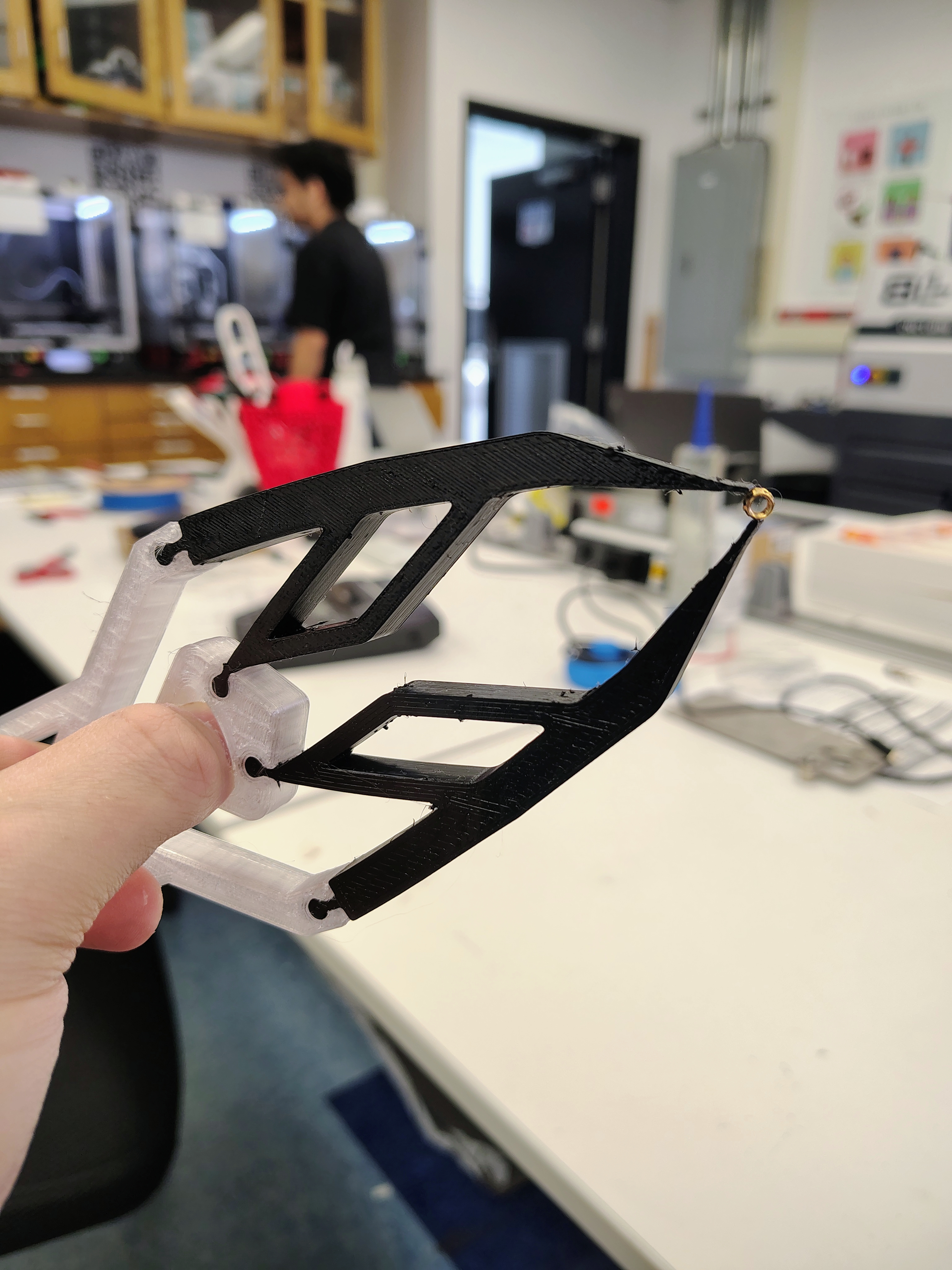
The pliers were developed through an iterative design process focused on combining rigid and flexible elements into a functional gripping tool. The assembly consisted of a rigid handle and ring structure with flexible prongs that acted as a compliant mechanism. These prongs were mechanically linked to both the handle and the ring such that pulling the ring toward the handle induced controlled bending, causing the jaws to converge. This configuration allowed a gripping motion to be achieved without traditional pin joints.
To support this approach, PETG was chosen for the rigid components due to its strength and dimensional stability, while TPU 95A was used for the flexible prongs to allow repeated elastic deformation without failure. Although the design was conceived with print-in-place principles in mind, the components were initially printed separately and assembled via press-fit connections.
Iteration 1
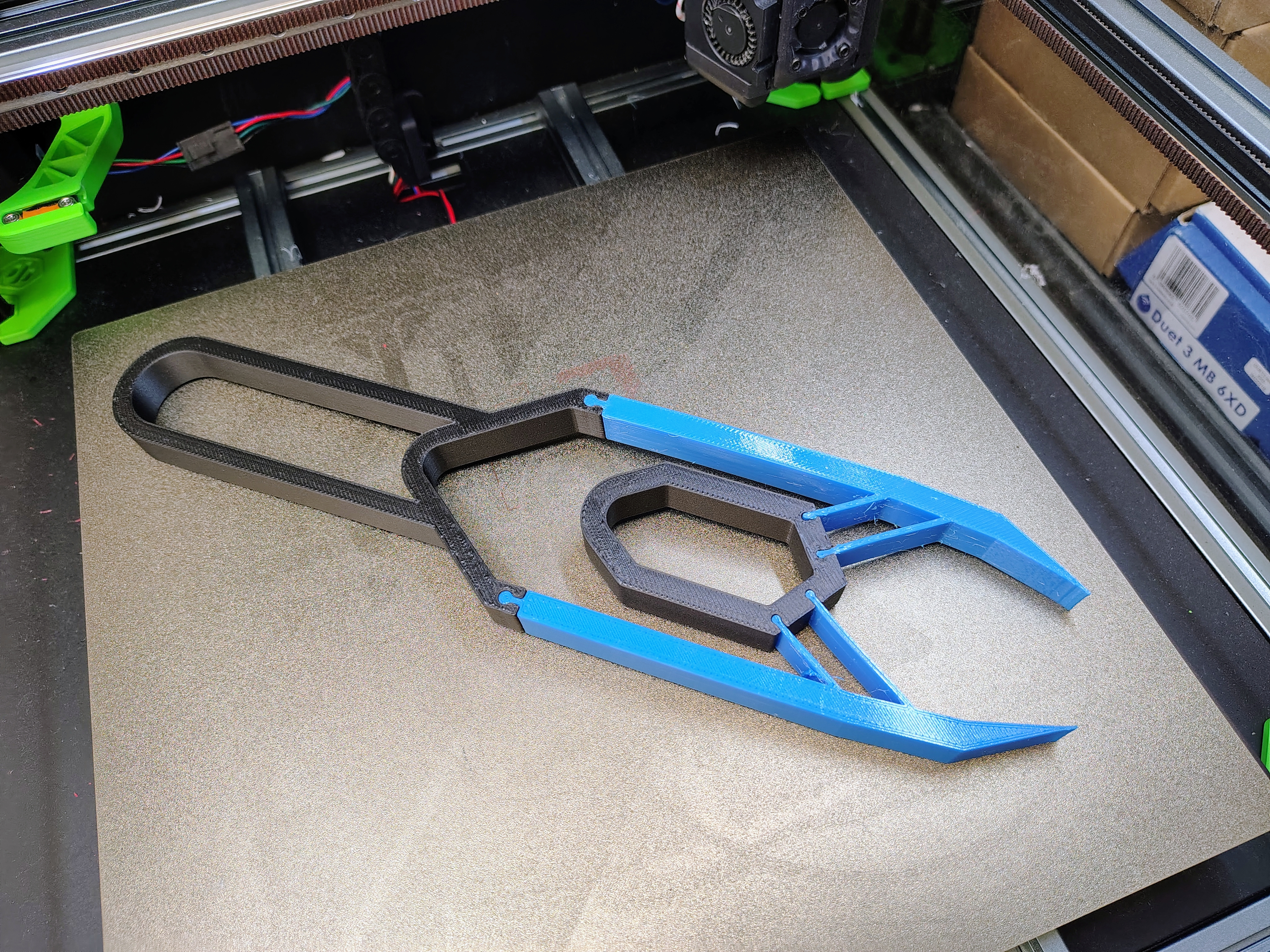
While the first prototype could open and close, a large amount of force was required to bring the tips into contact, and even when fully closed, the jaws often failed to align properly. The result was a staggered, uneven tip interface that made precisely gripping small objects difficult.
To address these issues, the second iteration was designed with shorter prongs and a reduced thickness. These changes produced a tool that was noticeably smaller and lighter, while also reducing the stiffness of the compliant elements enough to improve responsiveness.
Iteration 2
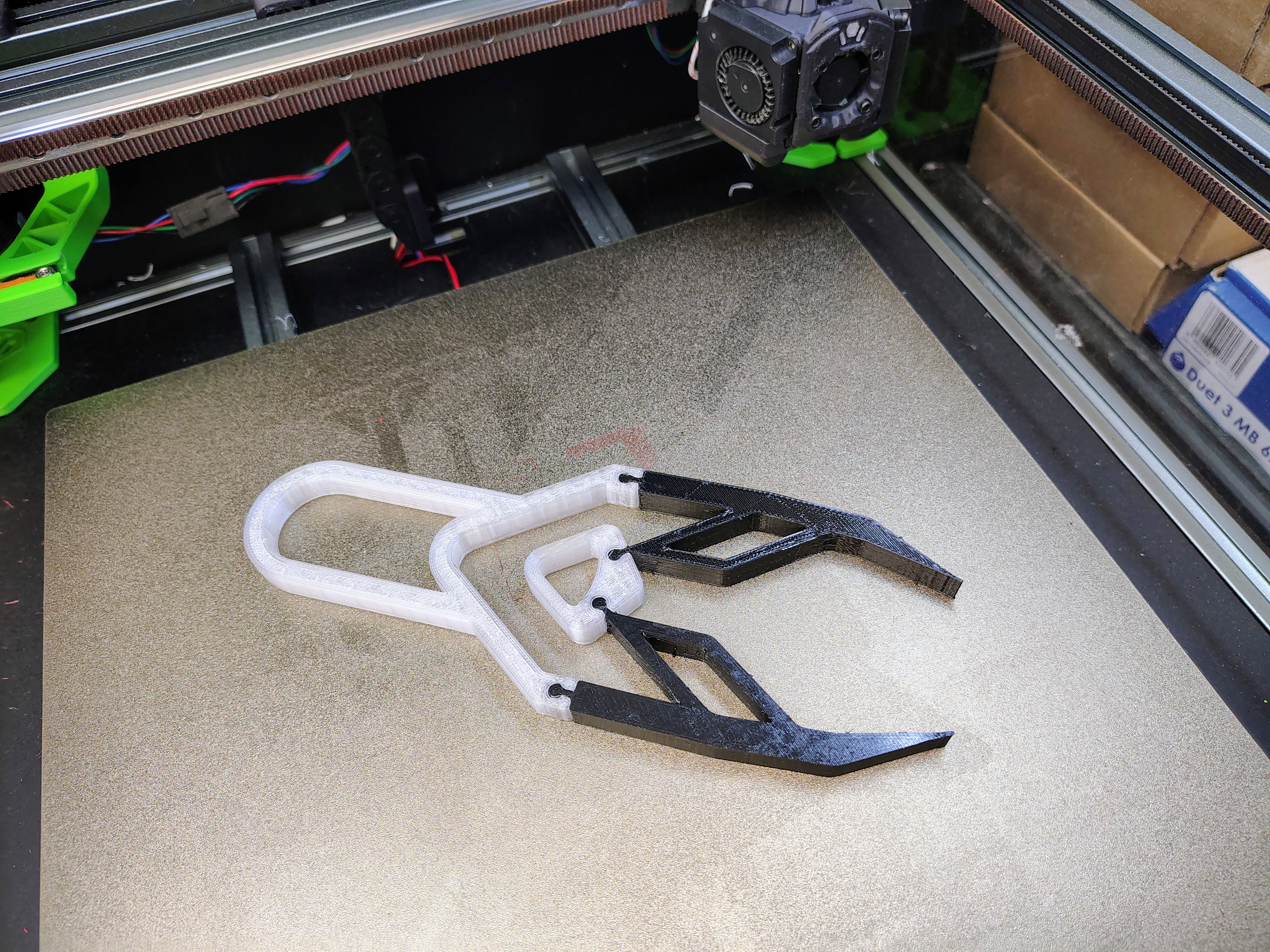
With these changes, the pliers closed much more smoothly and required significantly less force to operate. The reduced prong length improved alignment at the jaws, leading to better contact. The slimmer profile also made the tool feel less bulky during use.
The new iteration showed a considerable improvement in precision, reliably gripping small objects such as an M3 threaded insert with ease.
Interactive CAD Model
Geometric Specifications
| Specification | Value |
|---|---|
| Overall Length | 216 mm |
| Handle Length | 82 mm |
| Jaw Length | 106 mm |
| Handle Width | 44 mm |
| Jaw Width (Outer Prongs) | 80 mm |
| Jaw Width (Tip) | 42 mm |
| Tool Thickness | 10 mm |
| Grip Span (Open) | 23 mm |
| Grip Span (Closed) | 17 mm |
The grip span is the distance between the ring and the handle. When the ring is pulled towards the handle to close the pliers, grip span decreases.
Print Settings
All components were fabricated using an FDM 3D printer (Voron) with the print parameters summarized below. Settings were selected to balance strength and flexibility for both rigid and compliant components.
Stiff Components (PETG)
| Parameter | Value |
|---|---|
| Material | PETG |
| Nozzle Size | 0.6 mm |
| Infill Density | 15% |
| Sparse Infill Pattern | Rectilinear |
| Top Infill Pattern | Monotonic |
| Perimeters (Contour) | 3 (minimum) |
| Top Solid Layers | 3 |
| Bottom Solid Layers | 3 |
| Min Top Shell Thickness | 0.8 mm |
| Min Bottom Shell Thickness | 0.8 mm |
| First Layer Nozzle Temp | 245 °C |
| First Layer Bed Temp | 80 °C |
| Other Layers Nozzle Temp | 240 °C |
| Other Layers Bed Temp | 75 °C |
Flexible Components (TPU 95A)
| Parameter | Value |
|---|---|
| Material | TPU 95A |
| Nozzle Size | 0.6 mm |
| Infill Density | 25% |
| Sparse Infill Pattern | Gyroid |
| Top Infill Pattern | Monotonic |
| Perimeters (Contour) | 2 (minimum) |
| Top Solid Layers | 4 |
| Bottom Solid Layers | 3 |
| Min Top Shell Thickness | 0 mm |
| Min Bottom Shell Thickness | 0 mm |
| First Layer Nozzle Temp | 235 °C |
| First Layer Bed Temp | 60 °C |
| Other Layers Nozzle Temp | 230 °C |
| Other Layers Bed Temp | 60 °C |