Microfluidic Pinch-Flow Fractionation
About Pinch-Flow Fractionation
Pinch-flow fractionation (PFF) is a microfluidic technique used to separate particles based on size by leveraging laminar flow behavior at small scales. In a typical PFF device, a particle-containing stream is compressed (or “pinched”) by a buffer flow, forcing particles into predictable streamline positions based on their diameter. As the channel expands into a broader region, particles follow these streamlines and can be spatially separated into different outlet channels.
Compared to traditional filtration methods, PFF runs more reliably with less risk of clogging, making it well-suited for applications in biomedical diagnostics and particle analysis.
Design Overview
The goal of this project was to design and fabricate a microfluidic device capable of separating particles into two size ranges:
- Small particles: 125–150 μm
- Large particles: 425–500 μm
The device was produced using SLA resin printing to create a mold, followed by PDMS casting and bonding to a glass substrate.
The core geometry of the device includes:
- Two inlet streams (particle-containing flow and buffer flow)
- A pinched section where particles are laterally compressed
- A broad expansion region where particles separate along streamlines
- Three outlet channels (small particles, large particles, buffer)
A key challenge in this design was balancing flow resistance across outlets to ensure particles were collected in the correct streams.
Design Justification
The design of the outlet geometry was determined by both analytical predictions of particle trajectories and practical considerations related to flow resistance and manufacturability.
Streamline-Based Particle Positioning
The vertical position of a particle after exiting a pinched region can be described by:
Y0 = (wp − D/2) · (wb / wp)
where:
- wp is the width of the pinched section
- wb is the width of the broad section
- D is the particle diameter
- Y0 is the distance from the wall to the particle streamline in the broad section
This equation predicts that larger particles will be positioned farther from the wall after separation, while smaller particles remain closer to the wall. Using this relationship, approximate streamline positions were calculated for both target particle size ranges.
These predictions were then used to determine the placement of outlet boundaries. Specifically:
- The top outlet was aligned to capture smaller particles
- The middle outlet was aligned to capture larger particles
- The bottom outlet was reserved for the buffer layer, which contains no particles
This approach ensured that outlet placement was directly tied to expected flow behavior.
Flow Distribution and Outlet Sizing
The outlet widths were selected to achieve an approximate flow distribution of:
- 20.5% → Small particle outlet (top)
- 25% → Large particle outlet (middle)
- 54.5% → Buffer outlet (bottom)
This distribution reflects the physical reality of pinch-flow systems, where the buffer stream occupies a larger portion of the channel and must carry the majority of the volumetric flow.
Hydraulic Resistance Balancing
In microfluidic systems, flow rate through each outlet is governed by the relationship:
Q = ΔP / Rh
where Rh is hydraulic resistance.
For rectangular microchannels, resistance scales proportionally with channel length and inversely with channel width. Thus, to regulate flow into the particle outlets, both were designed to have higher hydraulic resistance than the buffer outlet by making them:
- Longer
- Narrower
- Serpentine in shape
The serpentine geometry increased channel length and channel resistance, helping to prevent excessive flow through the particle outlets and instead divert more flow towards the buffer outlet.
Design Tradeoffs
The outlet design represented a balance between competing requirements:
-
Too little resistance in particle outlets → Excess flow enters these channels, blurring separation
-
Too much resistance in particle outlets → Flow is diverted away, potentially pushing particles into incorrect outlets
The selected geometry aimed to strike a compromise:
- Sufficient resistance to maintain separation integrity
- Enough flow to reliably transport particles into their designated outlets
Interactive CAD Model
Geometric Specifications
| Specification | Value |
|---|---|
| Device Length | 75 mm |
| Device Width | 50 mm |
| Broad Section Length | 15 mm |
| Channel Spacing | 1 mm |
| Edge Clearance | 3 mm |
| Inlet/Outlet Diameter | 2.2 mm |
Fabrication Process
The device was fabricated using SLA printing to produce a mold, followed by PDMS casting.
SLA Mold Fabrication
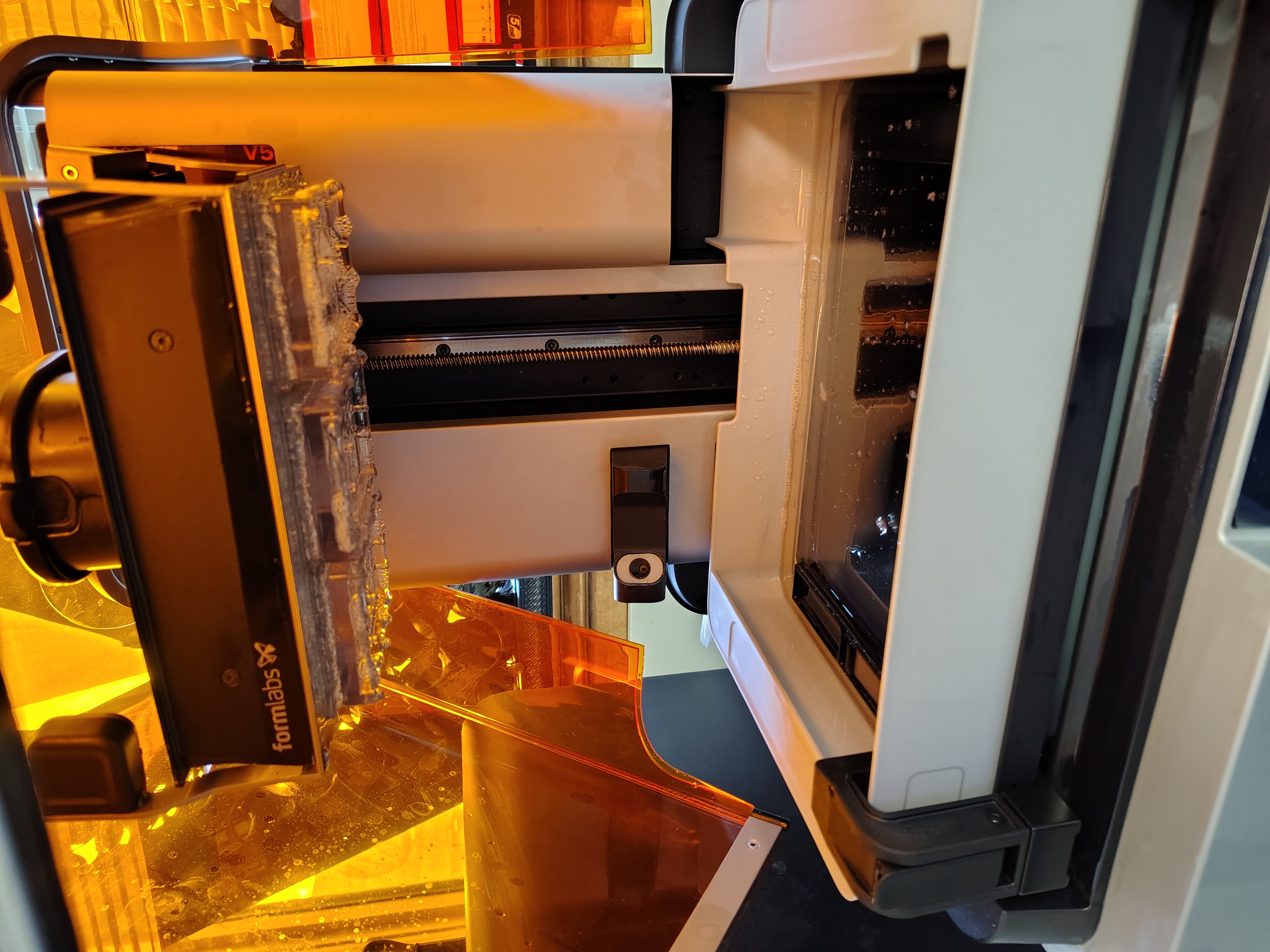
A Formlabs Form 4 printer was used to create the mold.
Washing
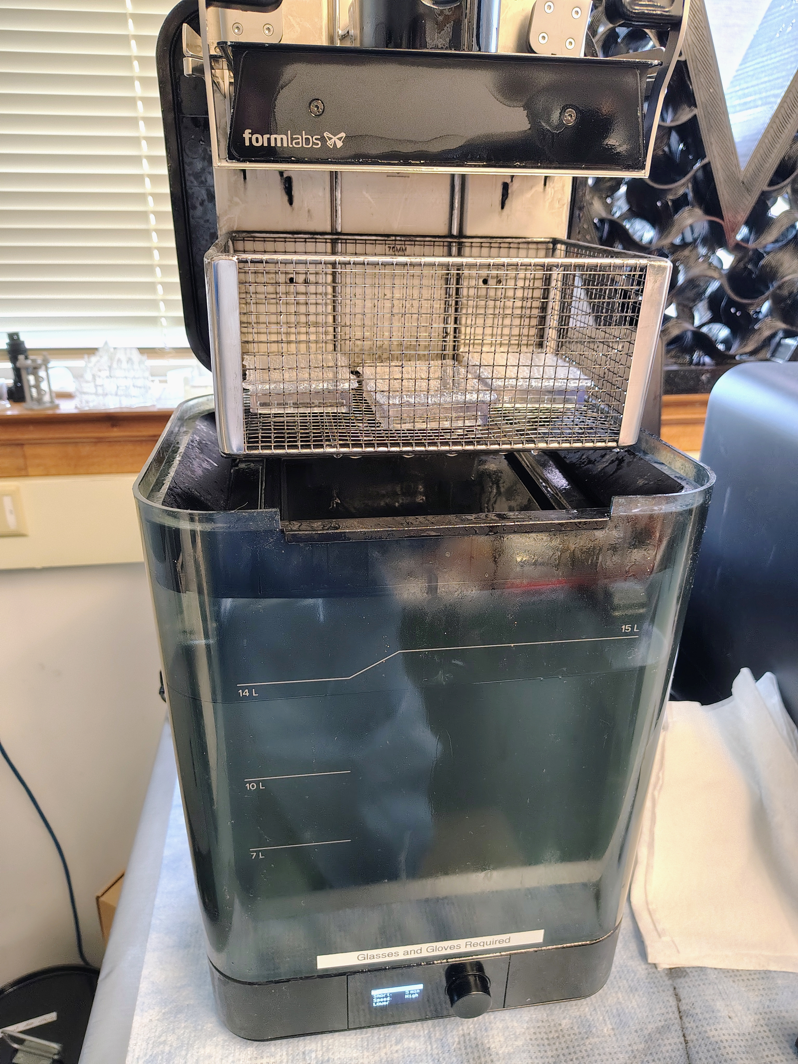
After printing, the mold was washed in isopropyl alcohol to remove uncured resin.
Drying
The mold was dried to prevent contamination and ensure proper curing.
UV Curing
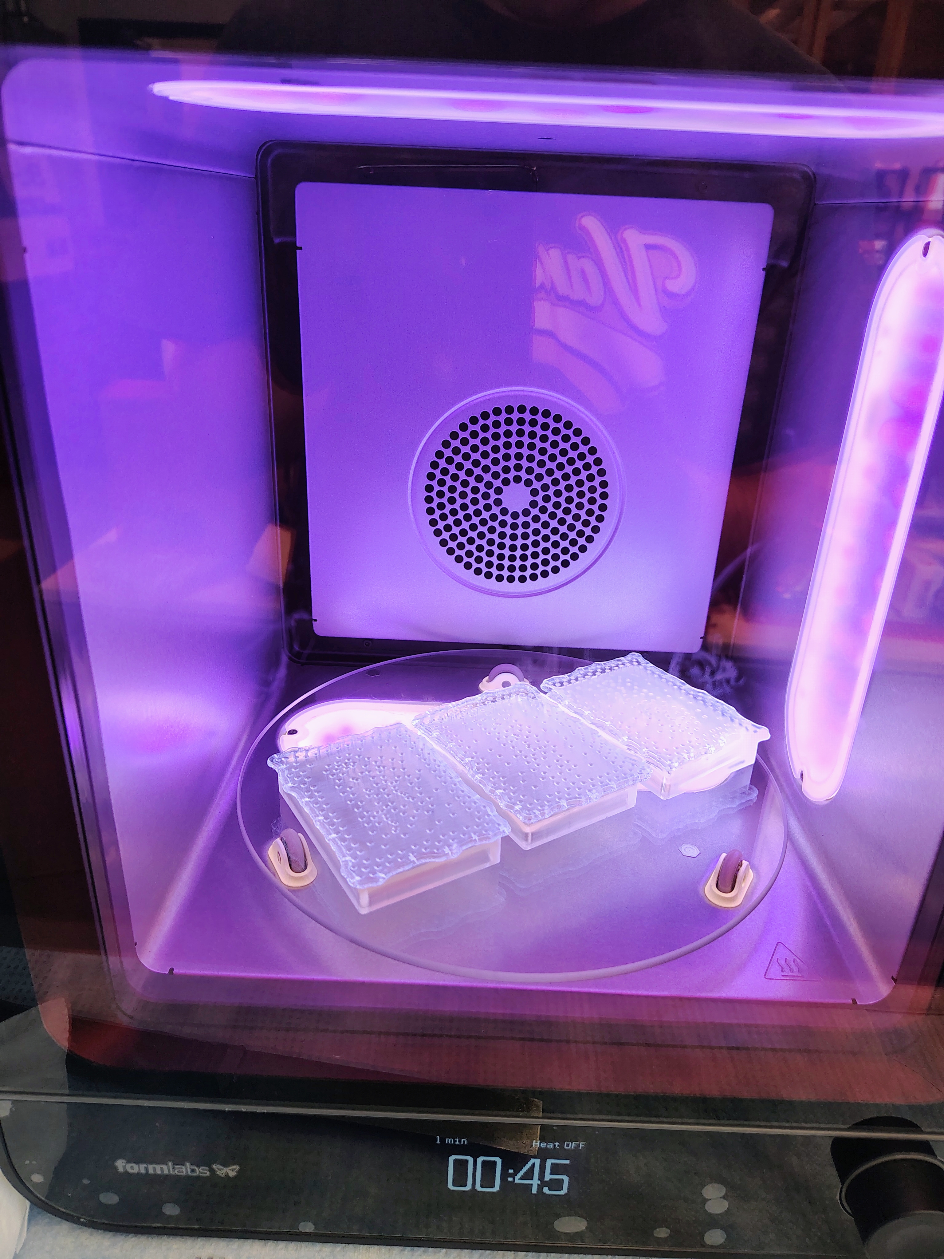
UV curing was then used to solidify the resin without causing warping.
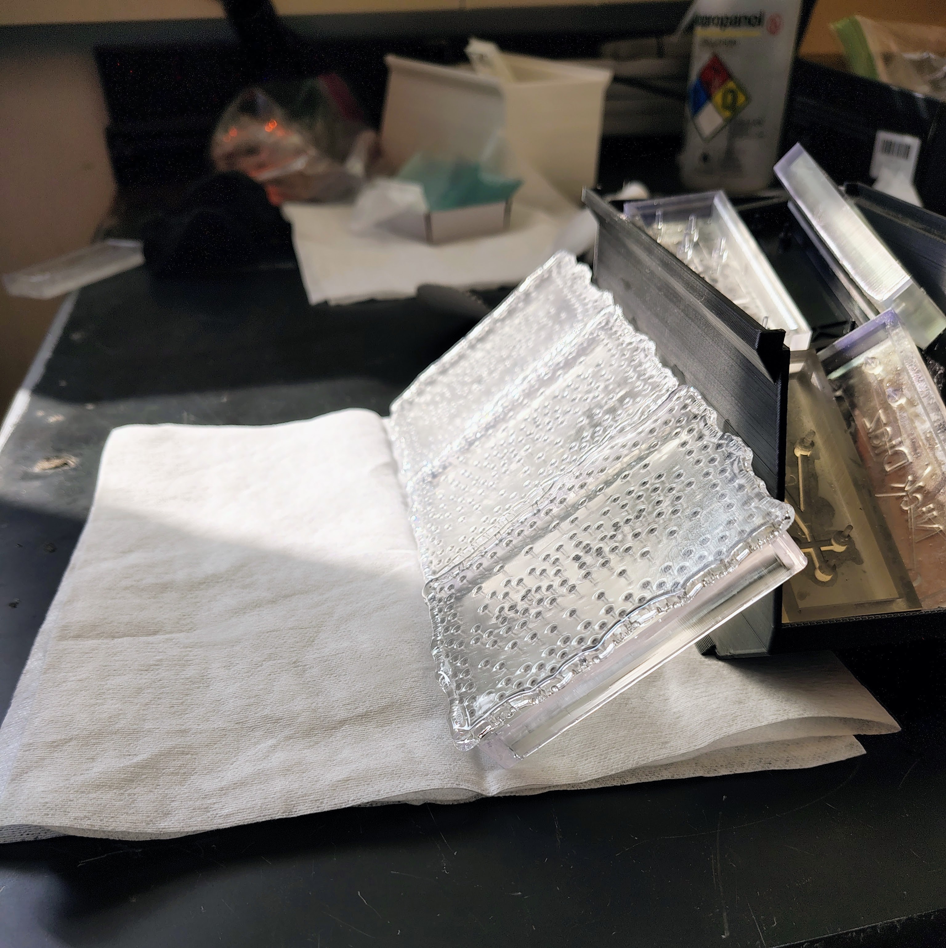
Final Mold
The completed mold shows clean channel features suitable for PDMS casting.
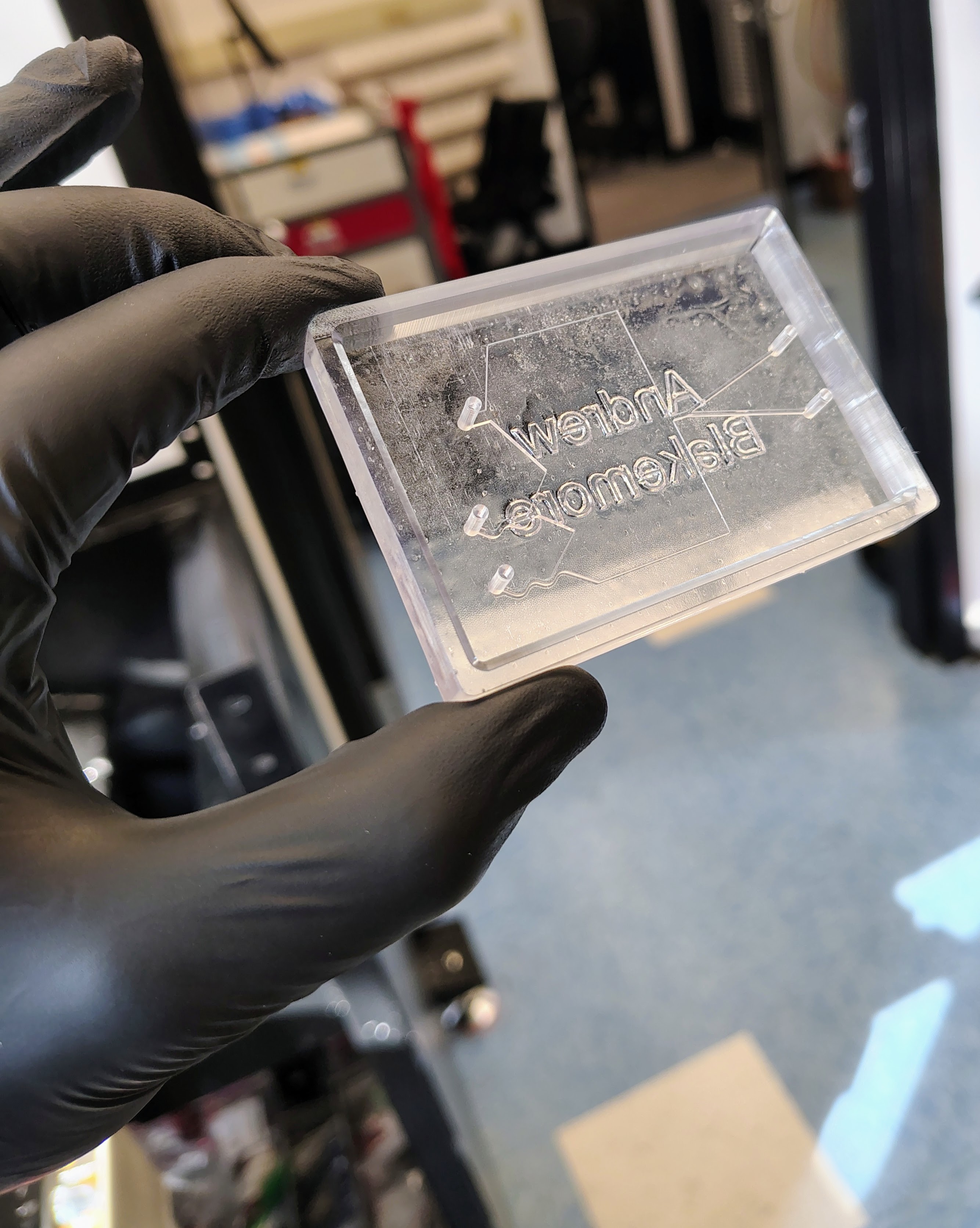
Device Assembly
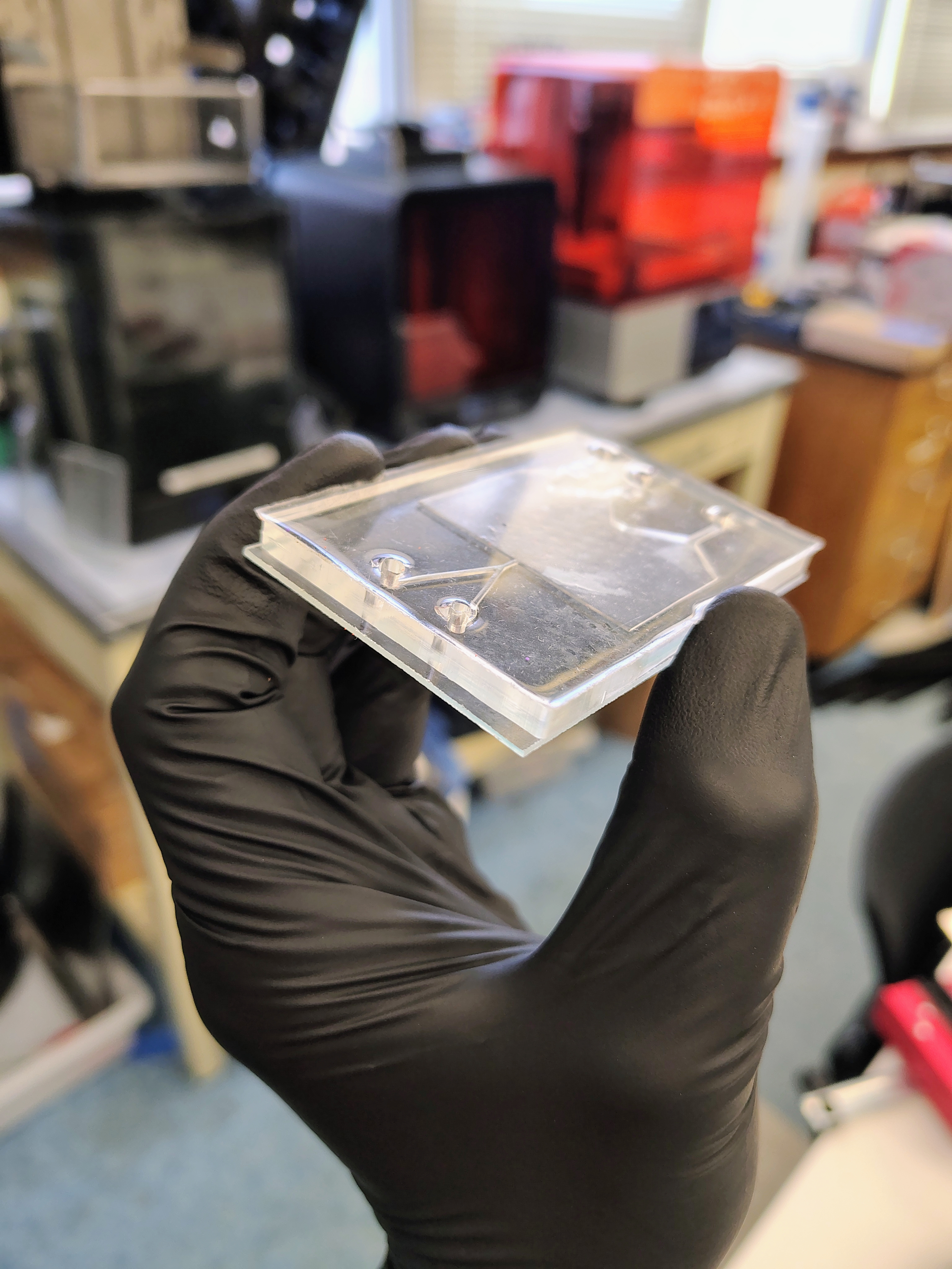
PDMS was poured over the mold, cured, and carefully removed. The device was then bonded to a glass slide to seal the channels.
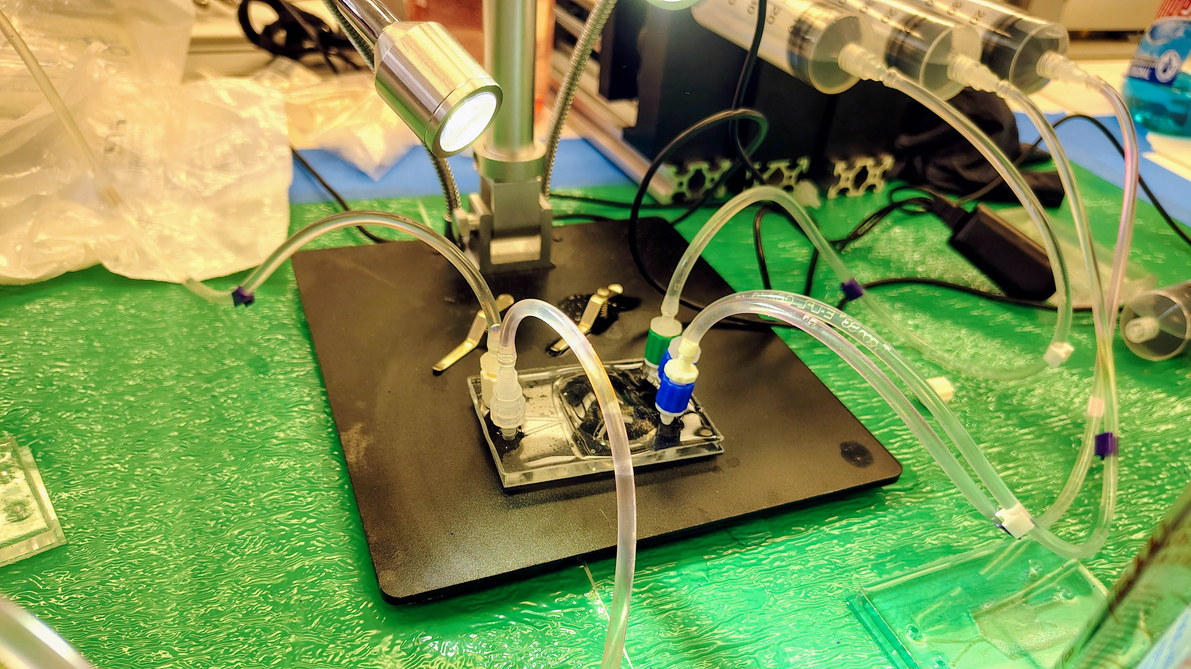
Testing Setup
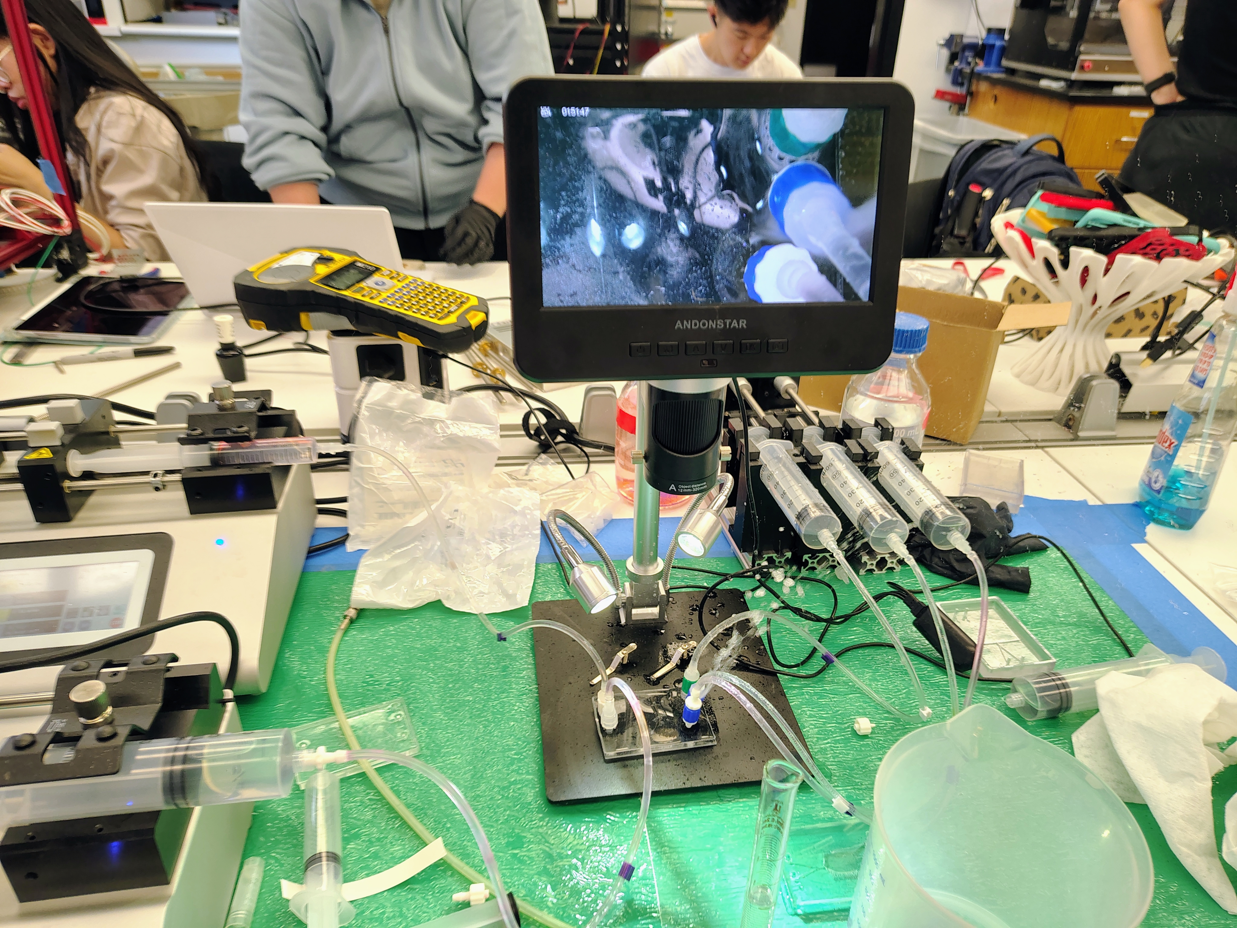
The device was tested using a dual-syringe pump setup to control buffer and particle flow rates.
Initial testing demonstrated:
- Stable laminar flow through the device
- Clear separation of particle streamlines after the pinched region
- Sensitivity to flow balance and air bubbles
However, insufficient separation distance before the outlet junctions, combined with imperfect flow resistance balancing, led to mixing between streams and prevented reliable particle sorting.
Future Direction
The device needs to be redesigned to utilize an enhanced pinch-flow fractionation (EPFF) approach. This method introduces a modified broadening region with a structured geometry that selectively expands the portion of the flow containing particles.
By amplifying the spacing between particle streamlines in this region, EPFF has been shown to significantly improve separation efficiency, reportedly achieving up to ~70% enhancement without introducing external forces.
This approach directly addresses the primary limitation observed in the current design: insufficient separation distance before outlet collection. Future iterations will focus on incorporating this geometry while maintaining manufacturability and flow stability.
Pinch-Flow Fractionation Video
This EPFF device serves as a reference for future iterations of my design:
Discussion
This project highlights the challenges of translating theoretical microfluidic concepts into functional devices. While the fabrication process using SLA printing and PDMS casting proved effective, achieving reliable particle separation requires careful control of channel geometry and flow resistance.
A transition to an EPFF design would be the natural next step to improve particle separation without increasing system complexity.